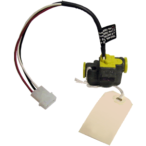
7:33 AM Fuel Flow Transducer 231 |
Different models of fuel flow transducer are available depending on the density and viscosity of the liquid to be measure. Here’s how it works in an aircraft; liquid enters through one side and enters the flow chamber. It follows a helical flow path, and exits vertically, thereby venting vapor bubbles that might form during the fuel flow. As the liquid flows, it has a velocity that can be measured and this velocity is directly proportional to flow rate. Inside the High Flow Transducer, is a miniature neutrally buoyant rotor finely balanced on jewelled bearings. As the fuel flows past the arms of the rotor, it pushes against the arms of the rotor and so, the rotor begins to spin. Now, on one side of the spinning rotor is an infrared light emitter while on the other side, is an infrared light detector. As the arms of the rotor spin, it interrupts an infrared light and this constant on-off is calculated to arrive at the spin rate and therefore, the fuel flow rate. Ingenious, simple and fool proof. Aircrafts use a more sensitive but rugged version of a typical fuel flow transducer. Rugged because a fuel flow transducer in aircraft needs to withstand aircraft engine vibrations, varying temperatures (-55°C to 70°C ) and varying pressures (up to 2,000 psi fuel pressure). It also has to meet FAA regulation regarding blocked rotor pressure drops. Installation of fuel flow transducer 231 in the engine. The fuel flow transducer 231 is to be mounted in a horizontal position with the wires facing upwards; this ensures that the rotor is in proper orientation vis-a-viz the internal Aircraft Fuel Flow monitor channel. This is vital otherwise the rotor will fail. Also, there should be no bend in the fuel pipe for up to 6 inches on either side of the fuel flow transducer. If the aircraft uses a carburetted engine, place the fuel flow transducer before the carburettor. If the transducer is going to be placed higher than the carburettor, insert an anti-siphon loop in the line that peaks higher than the transducer. If the aircraft uses an injected engine, place the fuel flow transducer between the engine fuel pump and the servo regulator. If the aircraft has as an fuel injected engine with vapor return lines, the fuel flow transducer needs to be placed between the servo regulator and the flow divider. Ideally, avoid mounting the transducer between the electric boost pump and the mechanical pump. Also, do not hard mount the transducer to the engine as violent vibrations may damage the internal parts of the transducer. For more information, please visit: https://www.jpinstruments.com/shop/fuel-flow-transducer-231/ |
|
|
| Total comments: 0 | |

