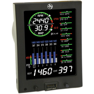
 For technicians about to install the JPI EDM 740 in an aircraft, this article is for you. It covers all the general points to installing the JPI EDM 740. For technicians about to install the JPI EDM 740 in an aircraft, this article is for you. It covers all the general points to installing the JPI EDM 740.
To start with, only FAA certified aircraft mechanic should attempt to install the EDM 740 in aircraft.
General Installation Instructions:
1.The EDM 740 (as do all EDM’s), are equipped with a delicate LCD display module. To prevent any damage to it, it is imperative that the mounting screws not penetrate the instrument by more than 0.12 inches. Ideally, use the steel template supplied with the installation kit.
2.The aircraft on which the EDM 740 is to be installed, should have necessary FAA approvals.
3.Special attention and care should be taken while crimping the wires. It is recommended that the technician fold back the wire double before crimping terminals.
4.Avoid aluminium fittings for planes equipped with FXT-201 or FXT-231 fuel flow transducer.
5.Before you begin, note down the K-factor (see side of the fuel flow transducer)
6.Map the holes and make sure there is nothing behind the panel that is likely to get damaged during the drilling process.
7.Provide service loops for all wires near the panel as well as near the engine (including Thermocouple wire) Service loops near the aircraft engine are required probes can be swapped for troubleshooting purposes.
8.Tie/keep wires away from heat sources.
9.Where soldering is required, use zinc chloride flux such as Nokorode brand.
10.Polarity of wires is vital and EDM Monitors 740 must be grounded at the engine, not at the avionics ground.
11.If the aircraft has a spark plug gasket probe, the CHT reading on that cylinder will be somewhat higher than cylinders with bayonet probes. Optionally, you could opt for an adapter probe (bayonet or screw-in) so that the factory CHT Probes and the JPI probe to be placed in the same bayonet location.
12.Wires from the Probes & Sensors should be routed through the firewall using fireproof rubber grommets and flame retarding silicone. Rather than drilling new holes, make use of existing holes.
13.Keep sufficient slack (but ensure the wires do not touch the engine surface). Secure the probe leads roughly 8 to 12 from the probe.
14.The JPI RPM Sensor kit comes with a 3-pin connector – please, only use this connector.
15.Make sure the wiring does not obstruct the controls or anything else under the panel.
16.Ensure the probe wires are not tied in with alternator, ignition or twin-engine cabin heater ignition wires as there is possibility of interference with temperature readings.
17.While power and ground wires are normal copper, the temperature probe wiring harness is made of Chromel-Alumel alloy wire (yellow). Do not substitute it or extend with normal copper wire – these are not compatible. Leads may be spliced only with additional Chromel-Alumel wire using copper butt splices.
18.On completion of the installation process, all wires should be secured using ties and carefully checked for rubbing, interference or chaffing with flight control cables or other moving parts.
For more information on J.P. Instrument’s EDM-740, please visit: https://www.jpinstruments.com/shop/edm-740-experimental-only-3/
|